Product presentation #
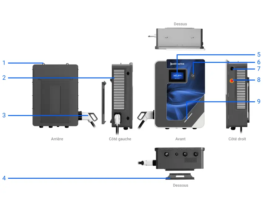
- Lifting rings
- Ventilation grille
- CCS T2 Combo socket
- Wall mounting bracket
- LCD touch screen
- RFID reader
- WiFi/4G antenna
- Emergency stop button
- Status indicator
LED indicators #
Blue: Standby
Red (steady or flashing) : Fault
Steady green: Charging in progress
Flashing green : Communication in progress
Flashing yellow: System initialization
Packing list #
| N° | Articles | Qty. |
|---|---|---|
| 1 | EV station | 1 |
| 2 | Instruction manual | 1 |
| 3 | Quality certificate | 1 |
| 4 | Wall mounting bracket | 1 |
| 5 | Cable holder | 1 |
| 6 | Exagonal head screws with expansion plugs M8*80/304 stainless steel | 9 |
Installation and wiring #
Wall installation #
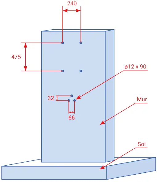
- First determine the height at which the terminal is to be installed, and deduce the location of the cable holder. Following the measurements shown in the drawing below, drill 4 holes in the wall for the mounting bracket, and three holes for the cable holder. Hammer the expansion plugs into the holes, then remove the screws and set them aside.
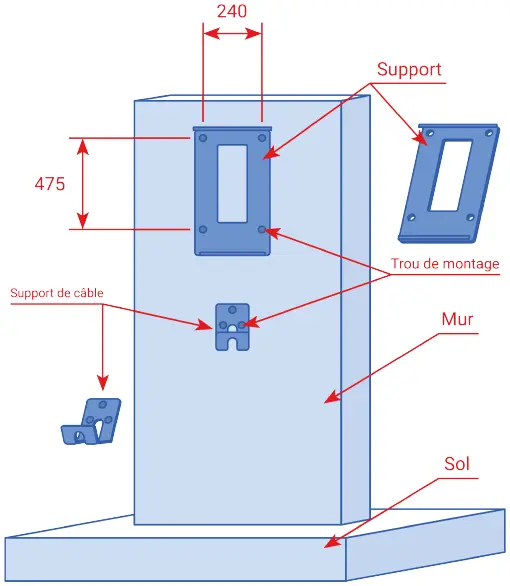
- Unscrew the two screws securing the mounting bracket to the lower part of the bollard, and set them aside. Place the mounting bracket on the previously fixed pins, and tighten the corresponding screws. Secure the cable holder using the same method.
- Once the bracket and cable holder have been secured, install the terminal on the mounting bracket. To do this, insert the upper part of the bracket into the slot at the rear of the bollard. Lock the bollard to the mounting bracket using the screws previously removed from the lower part of the bollard. Installation is now complete.
Pole-mounted installation #
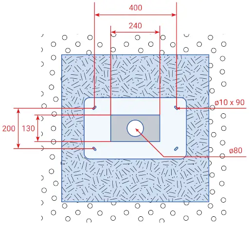
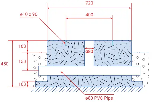
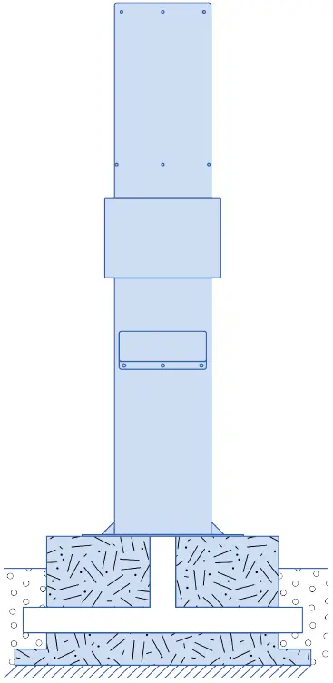
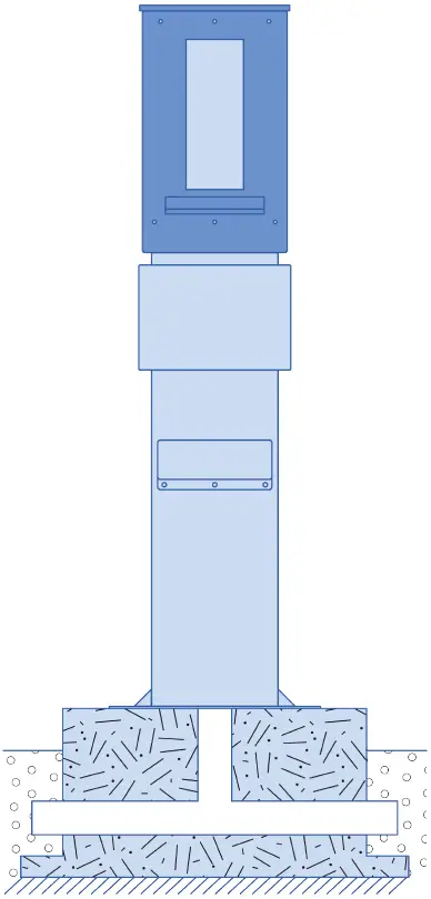
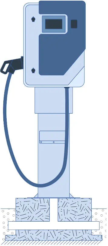
- You can install your WB-DC-40S or WB-DC-40D terminal on a WB-P2 mounting post (sold separately). Fix the post to a concrete slab according to the measurements below.
Pole-mounted installation #
- You can install your WB-DC-40S or WB-DC-40D terminal on a WB-P2 mounting post (sold separately). Fix the post to a concrete slab according to the measurements below.
- Unscrew the two screws securing the mounting bracket to the lower part of the bollard, and set them aside. Place the mounting bracket in front of the pole holes, and tighten the corresponding screws. Secure the cable holder using the same method.
- Once the bracket and cable holder have been secured, install the terminal on the mounting bracket. To do this, insert the upper part of the bracket into the slot at the rear of the bollard. Lock the bollard to the mounting bracket using the screws previously removed from the lower part of the bollard. Installation is now complete.
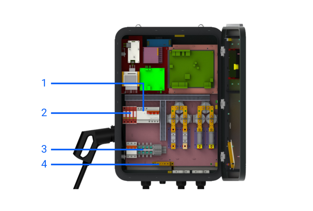
Wiring #
- RCBO AC input
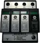
- Overvoltage protection device
- AC input terminal block. From left to right: L1, L2, L3, N.
- Earth connection.
Use 4 power cables and 1 PE cable, we suggest using a 5-conductor cable (with PE included / 5G16) for the convenience of using the watertight cable gland. Live wires must measure at least 16 mm², PE must be larger than 10 mm². The PE wire must be crimped onto an M6 ring terminal.
Overvoltage protection device
- List item #1
- List item
| Power output | L1 | L2 | L3 | PE | |
|---|---|---|---|---|---|
| Terminal | 40kW | Red | Black | Grey | Yellow & Green |
| Cable | 40kW | ≥16mm² ≥AWG5 |
≥16mm² ≥AWG5 |
≥16mm² ≥AWG5 |
≥16mm² ≥AWG5 |
NB 1. Only a P3-qualified I.R.V.E. technician can wire your terminal block. The AC power supply must be connected in the order of the phases marked on the terminal block.
NB 2. The ground connection must be reliable and robust.
NB 3. Switch off the circuit breaker upstream of the terminal before repairing or maintaining it.
NB 4. Do not disassemble the bollard or any of its components without the express instruction of Wellborne’s technical department.
Parameter settings #
Once installation and wiring are complete, connect the charger to a computer and configure the settings via the computer’s web browser. The charger is now ready for use.
Setting via the WB Charge application #
To access your bollard’s parameters with the WB Charge application, please refer to our WB Charge Application page, in the “Setting Wellborne Product Parameters” chapter.
Setup via your computer #
To access your terminal settings with your PC (Windows 10 & 11) or Mac, please refer to our Technical Brochure page, chapter “Setting Wellborne product parameters via a computer“.
The different charging modes of your terminal #
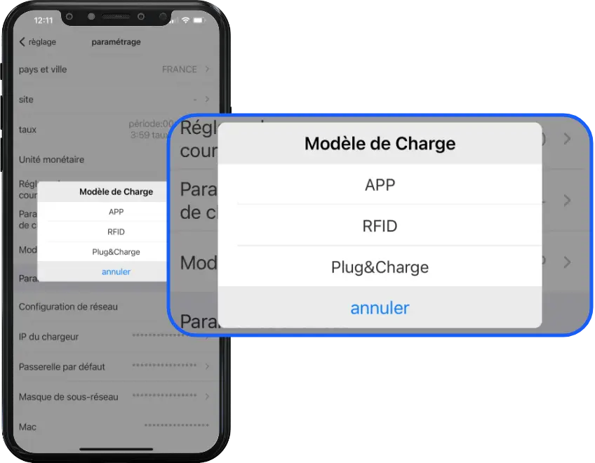
There are three operating modes for your Wellborne charging station: APP, RFID and Plug & Charge.
APP mode (third-party system operation: APP/RFID) #
With the WB Charge application, you can start or stop a charge, manage authorized users, tariffs and more. For more information on how to use the WB Charge application, please refer to the WB Charge application.
RFID mode #
In RFID mode, charging can only be initiated by swiping an RFID card over the terminal’s reader. For more information on how to set up your reader/configurator and RFID cards, please refer to our Technical Brochure, chapter “RFID card configurator“.
Plug & Charge mode #
Plug & Charge mode enables you to start charging a vehicle as soon as it is connected to your charging station. If you wish to interrupt charging, simply press the on/off button above the T2 socket.
Anomalies #
Troubleshooting #
In the event of a fault, users can check the information indicated by the LED. Each fault is indicated by a number of flashes and a color. If several faults occur at the same time, each sequence is displayed in chronological order at 3-second intervals. To find out more about diagnosing faults on your terminal, please refer to the “DC Fault Diagnostics” page.
Dynamic energy control & solar management #
For dynamic energy control and solar management of your bollard via the application, PC or Mac, please refer to our page “Setting Wellborne product parameters via the WB Charge application“, or “Accessing Wellborne product parameters via a computer“.
Technical specifications #
QUICK SOLO 40 kW (WB-DC-40S)
| SPECIFICATIONS | WB-DC-40S |
|---|---|
| IN & OUT | |
| Input voltage | 260~530V AC |
| Nominal input voltage | 400V AC |
| Input frequency | 50 / 60Hz |
| DC output voltage | 150~1000V |
| Max. input current | 64A |
| Power module reference | 2x UR100020-SW 20kW 1000/50A |
| Max. output power | 40kW |
| Max. output current | 100A |
| Voltage accuracy (DC) | <±0.5% |
| Current accuracy (DC) | ≤ ± 1% (at 20% ~ 100% of rated power) |
| Voltage regulation accuracy | ≤±0.5% |
| Current regulation accuracy | ≤±1% |
| Ripple coefficient (DC) | RMS: ≤±0.5%; Peak: ≤±1% |
| Measurement accuracy | 0.5% |
| Efficiency | ≥95.2% |
| Charging interface type | CCS Type 2 (standard) |
| Connection | Pistol |
| Cable length | 5m |
| Number of charging points | 1 |
| PROTECTION | |
| Overvoltage detection | Yes |
| Undervoltage detection | Yes |
| Overload detection | Yes |
| Short circuit detection | Yes |
| Earth leakage detection | Yes |
| Overheating detection | Yes |
| Lightning detection | Yes |
| FUNCTIONS & ACCESSORIES | |
| Ethernet / WIFI / 4G | Yes / Yes / Opt |
| LCD | 7-inch touch screen |
| Recommended protection | MCCB 80A |
| Access control | RFID / QR / APP |
| LED indicator | Yes |
| Emergency stop button | Yes |
| Pro-earth | Yes |
| MID metering | Opt |
| WORKING ENVIRONMENT | |
| Protection class | IP54 |
| Shock resistance | IK10 |
| Operating temperature | -25°C ~+50°C |
| Relative humidity | 5%-95% non-condensing |
| Maximum altitude | <2000 m |
| Cooling | Forced air cooling |
| Standby power consumption | <25W |
| Noise emission | ≤65db |
| MECHANICS | |
| Dimension (W / H / D) | 632 / 858 / 299.5 mm |
| Weight (kg) | 84.35 kg |
| Packaging dimensions (W / H / D) | – |
| CERTIFICATIONS | |
| Certificate | CE |

