Introduction #
This document describes the specifications of the FAST COMBO 44 AC / 60 DC station (WB-DC-AC44S/DC60D) and how to install and set up your station.
To help you better understand and use this product, the User’s Manual provides a detailed introduction to the functions, installation, operation and maintenance of the FAST COMBO station.
This manual is indispensable when installing, monitoring, debugging and maintaining the station.
Product presentation #
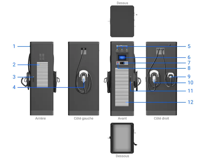
- WiFi/4G antenna
- Hot air outlet grille
- Rear door lock
- DC output – A
- Status indicators
- LCD touch screen
- RFID reader
- Emergency stop button
- AC output
- DC output – B
- Front door latch
- Cold air inlet grille
Packing list #
Installation and wiring #
| N° | Items | Qty. |
|---|---|---|
| 1 | EV station | 1 |
| 2 | Link to user manual | 1 |
| 3 | Quality certificate | 1 |
| 5 | RFID card | 3 |
| 6 | Expansion dowel with hexagonal head M8*80/304 stainless steel | 9 |
Floor installation #
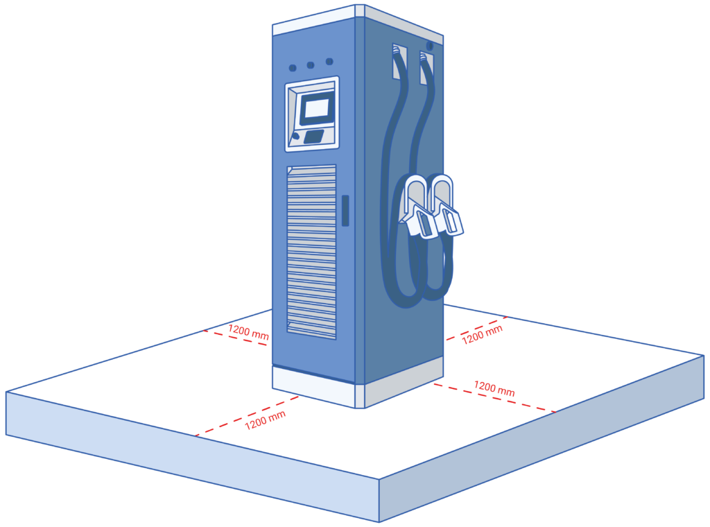
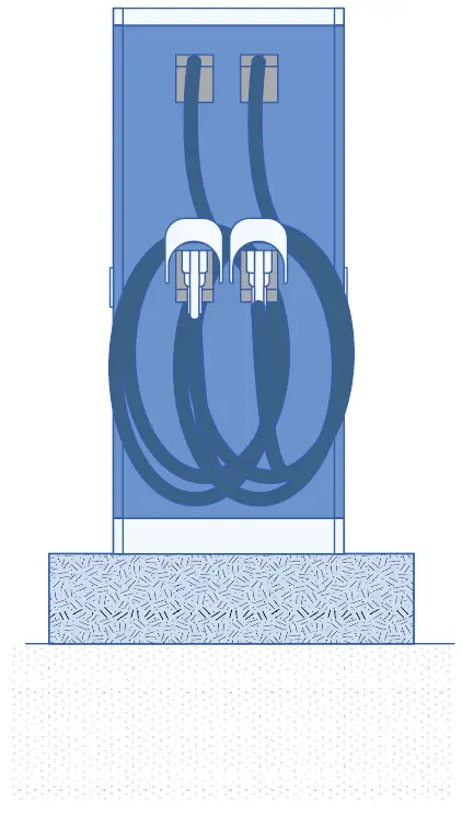
- Keep a minimum clearance of 1.2 m around the station.
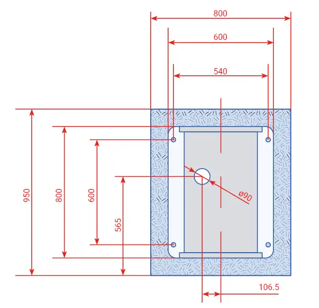
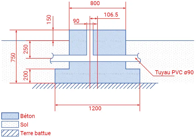
- The station must be installed on a customized concrete foundation.
- The foundation pile must be compacted. In soft, damp soil, the foundation must be reinforced. The foundation should rest on the highest point in the area to avoid flooding.
- The foundation pile must be made of reinforced concrete, requiring a minimum admissible bearing pressure of 1000 kg / square meter for the base.
- Construct the main grounding busbar (busbar) and electrode according to substation grounding regulations. The grounding resistance must be less than 4Ω, a flat galvanized steel 50 x 4 is suggested.
- The cable conduit uses 90 mm diameter PVC, the direction must be determined according to the situation on site, while the quantity depends on the number of HV / LV cables that will be used (use a redundant design).
- A level bar should be used to level the foundation.
- The internal foundation level should slope slightly towards the water collection pit.
- The illustration is for reference only.
- The minimum height of the foundation is 150 mm above ground level, and the vertical inclination must be less than 5%.
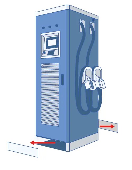
- First remove the plates at the front and rear of the station.
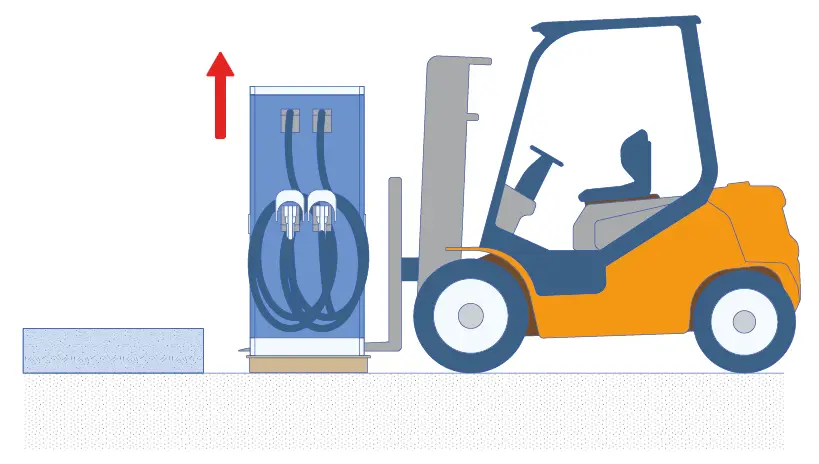
- Slide the forklift blades into the opening under the bollard, above the transport pallet. Raise the bollard and loosen the bolts holding the pallet, then remove the pallet.
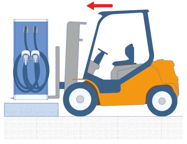
- Align the station on top of the concrete slab, taking care to center it and leave a gap of at least 1.2m on all four sides of the station.
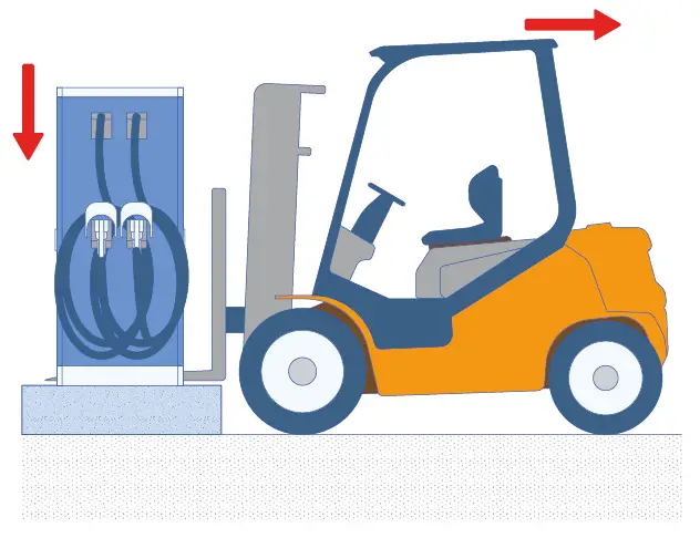
- Before lowering the station, make sure the cables coming from the concrete pad are accessible.
- Once the station has been placed on the base, use the fixing holes as a guide to drill the concrete block. Clean the holes, if possible with a vacuum cleaner, to ensure that they are not obstructed by dust or debris. Then insert the expansion plugs to secure the station to the concrete stud. The station is now ready for wiring.
Wiring #
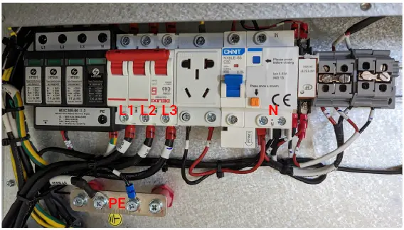
- Connect the three-phase, four-wire AC cables underground to the charger’s input terminal, respecting the color order and phase sequence. The earth cable must be connected to the charger’s earth bar. The wiring is illustrated below:
- Connect the charger’s earthing bar to the equipotential bonding bar at the installation site. The grounding cable must not be smaller than 25 mm². Grounding resistance must be less than 4Ω.
| Power output | L1 | L2 | L3 | N | PE | |
|---|---|---|---|---|---|---|
| Terminal | 60kW | Red | Black | Grey | Blue | Yellow & Green |
| Cable | 60kW | ≥35mm² ≥AWG2 |
≥35mm² ≥AWG2 |
≥35mm² ≥AWG2 |
≥35mm² ≥AWG2 |
≥35mm² ≥AWG2 |
Parameter settings #
Once installation and wiring are complete, connect the charger to a computer and configure the parameters via the computer’s web browser.
The charger is ready for use by default, but it is recommended that you put it online (remote diagnostics, change of charging mode, charging reports, etc.).
Setting via the WB Charge application #
To access your bollard’s parameters with the WB Charge application, please refer to our WB Charge Application page, in the “Setting Wellborne Product Parameters” chapter.
Setup via your computer #
To access your terminal settings with your PC (Windows 10 & 11) or Mac, please refer to our Technical Brochure page, chapter “Setting Wellborne product parameters via a computer“.
The different charging modes of your station #
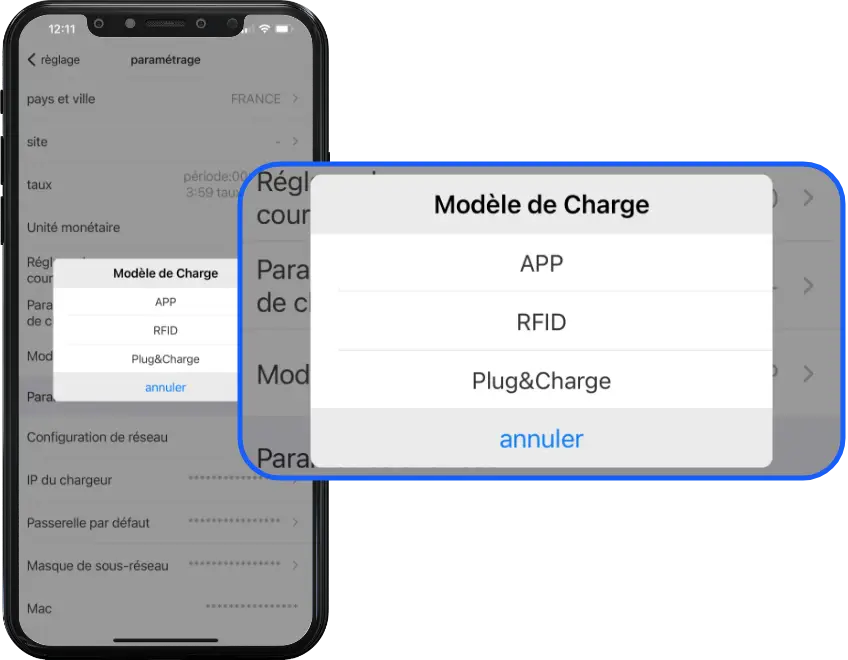
There are three operating modes for your Wellborne charging station: APP, RFID and Plug & Charge.
APP mode (third-party system operation: APP/RFID) #
With the WB Charge application, you can start or stop a charge, manage authorized users and tariffs, etc. For more information on how the WB Charge application works, please refer to the WB Charge application.
RFID mode #
In RFID mode, charging can only be initiated by swiping an RFID card over the terminal’s reader.
For more information on how to set up your reader/configurator and RFID cards, please refer to our Technical Brochure, chapter “RFID Card Configurator“.
Plug & Charge mode #
Plug & Charge mode allows you to start charging a vehicle as soon as it is connected to your charging station. If you wish to interrupt charging, simply press the on/off button above the T2 socket.
Anomalies #
Troubleshooting #
In the event of a fault, users can check the fault information on the LCD screen. Each fault is indicated by a number displayed on the LCD. If several faults occur at the same time, each number is displayed in chronological order at 3-second intervals. To find out more about diagnosing faults on your terminal, please refer to the “DC Fault Diagnostics” page.
Dynamic energy control & solar management #
For dynamic energy control and solar management of your bollard via the application, PC or Mac, please refer to our page “Setting Wellborne product parameters via the WB Charge application“, or “Accessing Wellborne product parameters via a computer“.
Technical specifications #
FAST COMBO 44 AC / 60 DC (WB-DC-AC44S/DC60D)
| SPECIFICATIONS | WB-DC-AC44S/DC60D |
|---|---|
| IN & OUT | |
| Input voltage | 260~530V AC |
| Nominal input voltage | 400V AC |
| Input frequency | 50 / 60Hz |
| DC output voltage | 150~1000V |
| AC output voltage | 400V |
| Max. input current |
95A + 63A = 158A |
| Power module reference | UR100040-SW 40kW 1000V/max100A |
| Max. DC output power |
60kW |
| Max. DC output current |
150A |
| Max. DC output current / gun |
150A |
| Max. AC output power |
43.6kW |
| Max. AC output current |
63A |
| Number of outputs | 1 AC output + 2 DC outputs |
| AC connection | IEC 62196-2, Type 2 (standard – Type 2S optional), Single output |
| DC connection | CCS T2 (standard), Dual output (shared charging mode) |
| Voltage accuracy (DC) | <±0.5% |
| Current accuracy (DC) | ≤±1% (at 20% ~ 100% of rated power) |
| Voltage regulation accuracy | ≤±0.5% |
| Current regulation accuracy | ≤±1% |
| Ripple coefficient (DC) | RMS: ≤±0.5%; Peak: ≤±1% |
| Measurement accuracy | 0.5% |
| Efficiency | ≥95.2% |
| Cable length | 5m |
| PROTECTION | |
| Overvoltage protection | Yes |
| Protection against undervoltage | Yes |
| Overload protection | Yes |
| Short-circuit protection | Yes |
| Earth leakage protection | Yes |
| Overheating protection | Yes |
| Lightning protection | Yes |
| FUNCTIONS & ACCESSORIES | |
| Ethernet / WIFI / 4G | Yes / Yes / Opt |
| LCD | 7-inch touch screen |
| RCD | DELIXI CDM6LI-125L – 125A – 6mA DC / Noark C63 3P typeA 30mA |
| Access control | RFID / QR / APP |
| LED indicator | Yes |
| Emergency stop button | Yes |
| Pro-earth | Yes |
| MID metering | Opt |
| Installation | Floor-mounted |
| WORKING ENVIRONMENT | |
| Protection class | IP54 |
| Shock resistance | IK10 |
| Operating temperature | -25°C ~+50°C |
| Relative humidity | %-95% non-condensing |
| Maximum altitude | <2000 m |
| Cooling | Forced air cooling |
| Standby power consumption | <80W |
| Noise emission | ≤65db |
| MECHANICS | |
| Dimension (W / H / D) | 600 / 1883 / 800mm |
| Weight (kg) | 330 kg |
| Packaging dimensions (W / H / D) | 870 / 2050 / 1070 mm |
| CERTIFICATIONS | |
| Certificate | CE |
Appendices #
Installation diagrams for dynamic energy control #
List of compatible Wellborne accessories #
RFID settings
WB-RFID
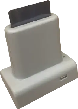
RFID card reader/configurator
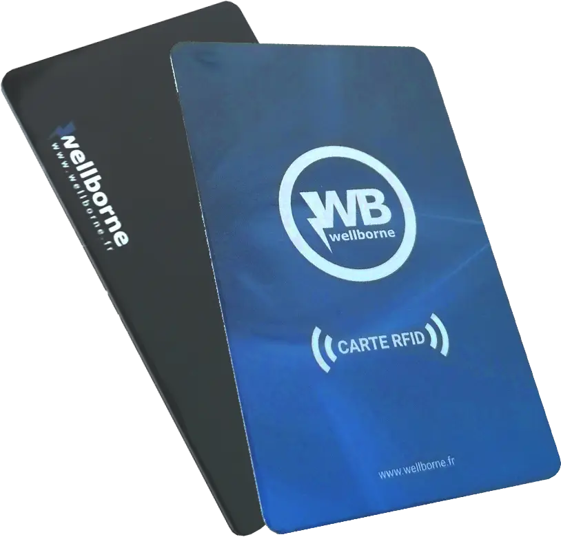
WB-RC
Pack of 10 RFID cards
Communication
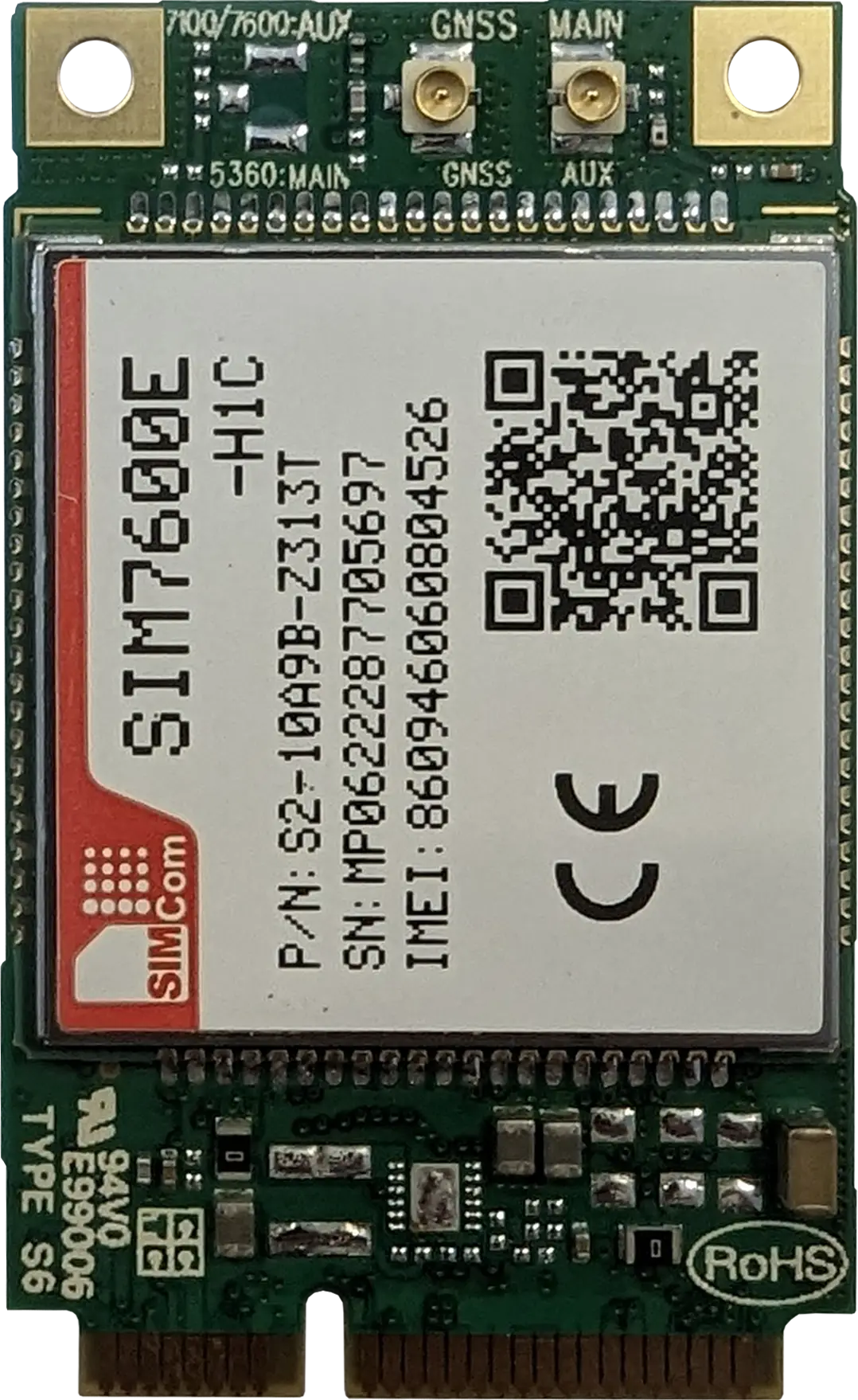
WB-4G
4G module
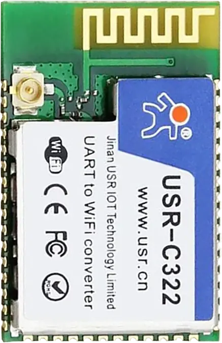
WB-W
Wi-Fi module
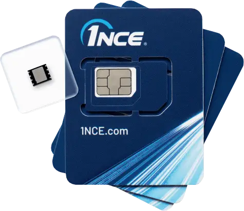
WB-SIM4G
SIM card

